
Fatigue analysis is not a single method but a family of approaches developed for different damage mechanisms and life regimes.
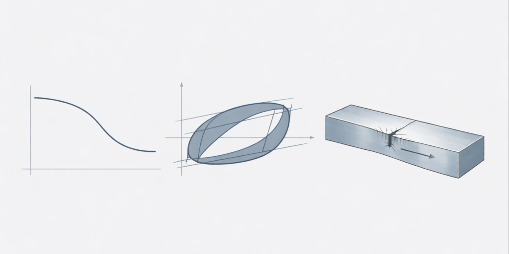
Three major fatigue-life methods are commonly used in engineering design:
- Stress-Life (S-N) Method
- Strain-Life (ε-N) Method
- Linear Elastic Fracture Mechanics (LEFM)
Although all three address fatigue failure, they are based on fundamentally different assumptions and are applicable in different design scenarios.
Understanding where each method belongs is essential for reliable fatigue assessment.
1. Stress-Life Method (S-N)
The Stress-Life method relates stress amplitude to the number of cycles to failure.
It is based on:
- Elastic stress analysis
- High-cycle fatigue behavior
- Endurance limit concept for steels
Applicable when:
- Cyclic stresses remain within the elastic range
- High-cycle fatigue dominates
- Crack initiation phase governs life
- No significant plastic deformation occurs
Typical applications:
- Rotating shafts
- Machine components under bending or torsion
- Preliminary design verification
The method is simple and efficient, but it does not explicitly model crack growth.
2. Strain-Life Method (ε-N)
The Strain-Life approach considers total strain amplitude instead of stress amplitude.
It is based on the Coffin-Manson relationship:
εa = εe + εp
Where total strain is decomposed into:
- Elastic strain component
- Plastic strain component
This method captures material behavior in the presence of cyclic plasticity.
Applicable when:
- Low-cycle fatigue is expected
- Plastic strains are significant
- High local stresses occur near notches
- Detailed material cyclic properties are available
Typical applications:
- Components subjected to overload cycles
- Start-stop loading conditions
- High stress concentration regions
The Strain-Life method provides higher accuracy but requires more material data.
3. Linear Elastic Fracture Mechanics (LEFM)
LEFM shifts the focus from crack initiation to crack propagation.
It assumes that:
- A crack already exists
- Linear elastic conditions apply
- Crack growth governs failure
The method uses stress intensity factors and Paris’ law:
da dN = C (ΔK)m
Where:
- a – crack length
- ΔK – stress intensity factor range
- C, m – material constants
Applicable when:
- Crack growth dominates fatigue life
- Inspection intervals are defined
- Damage tolerance design is required
- Large welded structures are assessed
Typical applications:
- Crane structures
- Welded joints
- Large steel frameworks
- Aerospace components
LEFM enables the prediction of the remaining useful life based on crack size.
High-Cycle vs Low-Cycle vs Crack Growth Regimes
The selection of fatigue method often depends on life regime:
- High-cycle fatigue → Stress-Life
- Low-cycle fatigue → Strain-Life
- Propagation-controlled life → LEFM
These regimes are not strictly separated but represent transitions in damage mechanisms.
Practical Engineering Perspective
In real engineering practice:
- Stress-Life is widely used for standard machine components
- Strain-Life is applied for local critical regions
- LEFM is used for structural integrity and damage tolerance assessment
No single method is universally correct. The appropriate approach depends on:
- Loading conditions
- Material behavior
- Required safety level
- Inspection philosophy
- Structural scale
Conclusion
Stress-Life, Strain-Life and LEFM are not competing methods but complementary tools within fatigue engineering. The key engineering decision is to identify which damage mechanism governs the component under consideration.
Selecting the appropriate fatigue framework is fundamental to achieving reliable life predictions and ensuring structural safety.