
Fatigue failure is one of the most common failure modes in rotating shafts. Even when static stresses are well below yield strength, cyclic loading may eventually lead to crack initiation and fracture.
The most traditional approach to fatigue assessment in mechanical design is the Stress–Life Method, also known as the S–N method.
This article outlines its theoretical basis, assumptions and practical limitations in shaft calculations.
1. Fundamental Concept of the S–N Method
The Stress–Life approach is based on the relationship between:
- Stress amplitude σa
- Number of cycles to failure N
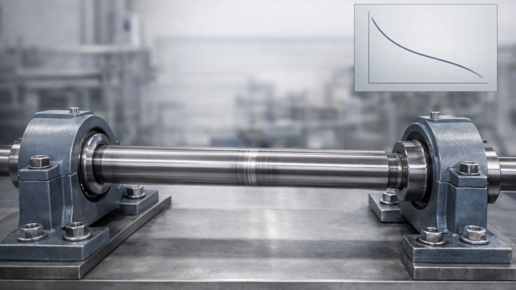
This relationship is represented by the S–N curve.
For many steels, the curve exhibits two characteristic regions:
- Finite life region at higher stress amplitudes
- Endurance region at lower stress amplitudes
2. Application to Shaft Design
In rotating shafts, fatigue loading typically arises from:
- Reversed bending
- Reversed torsion
- Combined bending and axial loading
For classical S-N analysis, the method assumes:
This condition corresponds to completely reversed loading, which is how standard laboratory S-N curves are generated.
Under this assumption, the alternating stress is directly compared with the corrected endurance limit.
3. Modification of the Endurance Limit
The laboratory endurance limit must be corrected to account for real operating conditions.
The modified endurance limit is defined as:
Se = kakbkckdkeS’e
where:
- ka – surface condition factor
- kb – size factor
- kc – load factor
- kd – temperature factor
- ke – reliability factor
These correction factors account for:
- Surface finish
- Component dimensions
- Type of loading
- Operating temperature
- Target reliability level
For example, increasing reliability from 95% to 99.9% significantly reduces the allowable endurance limit.
This adjustment is often underestimated in preliminary design.
4. Stress Concentration Effects
Real shafts contain geometric discontinuities such as:
- Shoulders
- Keyways
- Grooves
These introduce stress concentration.
The maximum local stress is given by:
σmax = Kfσ0
where Kf is the fatigue stress concentration factor. Unlike the theoretical stress concentration factor Kt, the fatigue factor accounts for material notch sensitivity.
Ignoring this distinction may result in non-conservative fatigue predictions.
5. Infinite Life vs Finite Life Design
The Stress–Life method allows two different design approaches:
Design for infinite life
The alternating stress must remain below the corrected endurance limit.
Design for finite life
The S-N curve is used to determine the number of cycles to failure:
N = ( σar a )1/b
Finite-life design becomes relevant when:
- High stress amplitudes are unavoidable
- Load cycles are limited and predictable
- Weight optimization is critical
6. Limitations of the Stress–Life Method
Despite its simplicity, the method has important limitations:
- Valid primarily for high-cycle fatigue
- Assumes elastic behavior
- Does not explicitly model crack growth
- Requires correction when mean stress is present
Most practical loading cases involve fluctuating stresses with non-zero mean stress. In such cases, additional fatigue failure criteria must be introduced.
Conclusion
The Stress-Life method remains a practical and efficient tool for shaft fatigue design, particularly in high-cycle applications.
When its assumptions are respected and correction factors are properly applied, it provides reliable results for preliminary sizing and verification.
However, its simplicity should not obscure its limitations. Understanding where the method applies is as important as knowing how to use it.