
Longitudinal and Transverse Actions on Runway Beams
In addition to vertical wheel loads, EN 1991-3 requires consideration of horizontal forces generated during crane movement.
These forces arise primarily from:
- Acceleration and braking of the crane bridge
- Acceleration and braking of the trolley
- Friction interaction between wheel and rail
They act along and across the runway beams and must be combined with vertical loads.
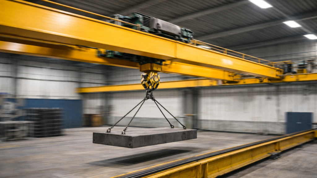
Longitudinal Forces from Crane Travel
During acceleration or braking of the crane bridge, inertia generates longitudinal forces along the direction of travel.
These forces depend on:
- The moving mass of the crane system
- The friction between wheel and rail
- The number of driven wheels
- The minimum vertical wheel load
The longitudinal force is transferred from wheels to rails and then into runway beams and supporting frames.
Although typically smaller than vertical reactions, these forces may govern connection design and anchor forces.
Transverse Forces from Crane Skewing
In practice, cranes do not always travel perfectly straight. Skewing may occur due to:
- Rail misalignment
- Unequal drive torque
- Geometric tolerances
- Structural deformation
This results in transverse horizontal forces acting perpendicular to the crane travel direction. These forces can significantly influence:
- Lateral bending of runway beams
- Rail fastening systems
- Bracing and frame stability
Skewing effects are particularly important for long-span or lightly braced structures.
Horizontal Forces from Trolley Movement
When the trolley accelerates or decelerates along the bridge, additional horizontal forces are generated.
A practical design rule is to take the horizontal force from trolley motion as a percentage of the sum of:
- Hoist load
- Trolley weight
According to EN 1991-3, horizontal forces related to trolley acceleration may be taken as 10% of the sum of the hoist load and the trolley weight.
This simplified rule provides a practical design value without requiring detailed dynamic modelling. These forces act on the girder and are transferred to runway beams through wheel reactions.
Load Distribution and Structural Response
Horizontal forces are not applied uniformly.
Their distribution depends on:
- Wheel spacing
- Number of girders
- Structural stiffness
- Position of the trolley
Accurate modelling of these forces ensures realistic support reactions and internal force distribution in runway beams.
Conclusion
Horizontal forces generated by crane acceleration, braking and trolley movement represent essential components of structural design for crane-supporting systems.
Although often smaller than vertical wheel loads, they directly affect longitudinal stability, lateral bending and connection forces. A complete crane load assessment must therefore include both vertical and horizontal actions to ensure safe and consistent structural performance.