
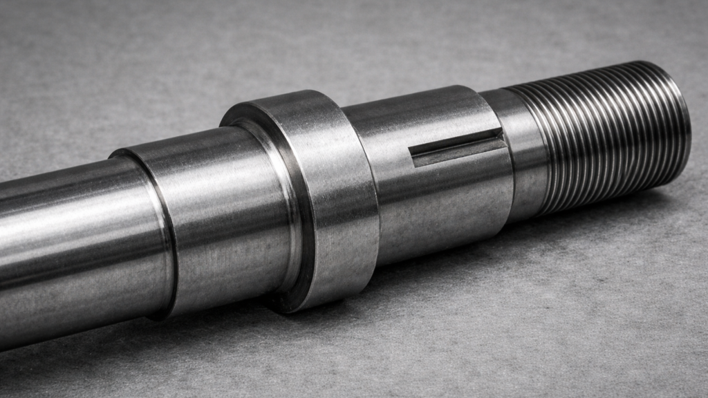
Real shafts are never perfectly smooth cylinders. They contain geometric discontinuities such as:
- Shoulders
- Fillets
- Keyways
- Grooves
- Threads
These features introduce local stress amplification known as stress concentration. In fatigue design, correctly accounting for this effect is critical.
Theoretical Stress Concentration Factor Kt
The theoretical stress concentration factor is defined as:
Kt = σmax σnom
Where:
- σmax – maximum local stress at the notch
- σnom – nominal stress
- Fillet radius
- Diameter ratio
- Notch depth
- Groove shape
It is obtained from handbooks, charts or finite element analysis. However, Kt does not fully describe fatigue behavior.
Why Kt Is Not Enough for Fatigue
In static loading, the full stress concentration applies.
In fatigue, materials are not always fully sensitive to notches. Due to microstructural effects and local plasticity, the effective fatigue stress concentration is typically lower than the theoretical value.
This leads to the introduction of the fatigue stress concentration factor.
Fatigue Stress Concentration Factor Kf
The fatigue factor is defined as:
Kf = σa,max σa,nom
It is related to the theoretical factor through:
Kf = 1 + q (Kt − 1)
Where:
- q – notch sensitivity factor
- 0 ≤ q ≤ 1
Notch Sensitivity q
The notch sensitivity factor describes how strongly a material responds to geometric discontinuities.
- q = 0 → material is insensitive to notches
- q = 1 → full theoretical stress concentration applies
Notch sensitivity depends on:
- Material strength
- Microstructure
- Notch radius
High-strength steels tend to be more notch-sensitive. Small notch radii increase sensitivity.
Engineering Implications for Shaft Design
In rotating shafts:
- Keyways significantly increase fatigue risk
- Small fillet radii can drastically reduce life
- Surface finishing near shoulders becomes critical
Even if nominal stress satisfies the endurance limit, the local alternating stress may exceed allowable limits once Kf is applied.
Failure to distinguish between Kt and Kf may result in:
- Overestimated fatigue life
- Undersized shaft diameter
- Premature crack initiation at geometric transitions
Interaction with Other Fatigue Factors
Stress concentration effects interact with:
- Surface finish
- Size factor
- Mean stress
- Residual stresses
In practical design, all corrections must be applied consistently before performing fatigue verification.
Conclusion
Theoretical stress concentration describes geometry. Fatigue stress concentration describes the material response to that geometry.
Using Kt directly in fatigue calculations may be overly conservative or, in some cases, incorrect.
The fatigue factor Kf, combined with notch sensitivity, provides a more realistic representation of fatigue behavior in notched components.
In shaft design, geometric transitions are often the governing locations for fatigue failure.
Accurate treatment of stress concentration is therefore essential for reliable life prediction.