
Why Trolley Position Governs Structural Design
One of the fundamental differences between ordinary structural beams and crane main girders is the presence of moving concentrated loads.
The trolley and hoisted load travel along the span, which means the internal forces in the girder are not constant. Instead, bending moment and shear vary depending on the trolley position.
Correct identification of the governing position is therefore essential in girder design according to FEM 1.001.
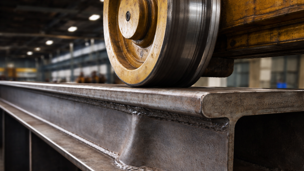
Nature of the Moving Wheel Loads
The crane girder is subjected to:
- Concentrated wheel loads
- Self-weight of the girder
- Trolley weight
- Hoisted load
Unlike uniformly distributed loading, these forces move along the span during operation. As a result:
- Bending moment diagrams change continuously
- Support reactions vary
- The most unfavorable internal force does not occur automatically at mid-span
Maximum Bending Moment Is Position-Dependent
For moving concentrated loads, the maximum bending moment occurs when the load configuration produces the most unfavorable internal force distribution.
In practical terms, this means:
- The trolley must be placed at the critical position
- Multiple load arrangements may need to be considered
- Wheel spacing influences the moment envelope
The governing bending moment corresponds to the trolley location that maximizes stress in the critical section of the girder.
Influence of Wheel Arrangement
Crane bridges typically have multiple wheels on each side.
The spacing between wheels affects:
- Reaction distribution
- Shear force peaks
- Shape of the bending moment envelop
Because loads are discrete and spaced, the bending response differs from a single-point load case. Design must therefore consider the real wheel configuration rather than a simplified equivalent load.
Why This Step Is Critical
If the most unfavorable trolley position is not identified:
- Bending stress may be underestimated
- Section modulus may be insufficient
- Fatigue stress range may be miscalculated
Static verification, fatigue assessment, and stability checks all rely on the correct determination of maximum internal forces.
The moving load problem is therefore not a secondary detail, but a governing design step.
Conclusion
In crane main girder design, the moving nature of wheel loads fundamentally affects internal force distribution. The maximum bending moment depends on trolley position and wheel arrangement, and must be determined through systematic evaluation of critical configurations.
Accurate identification of the governing load position forms the basis for subsequent static strength, fatigue and stability verification in accordance with FEM 1.001.