
Why Both Must Be Checked in Crane Design
In crane-supporting structures, design is governed not only by maximum wheel loads but also by minimum accompanying loads.
EN 1991-3 requires evaluation of both values because crane behavior produces uneven and shifting load distribution along the runway beams.
Ignoring minimum loads may lead to unsafe or incomplete structural verification.
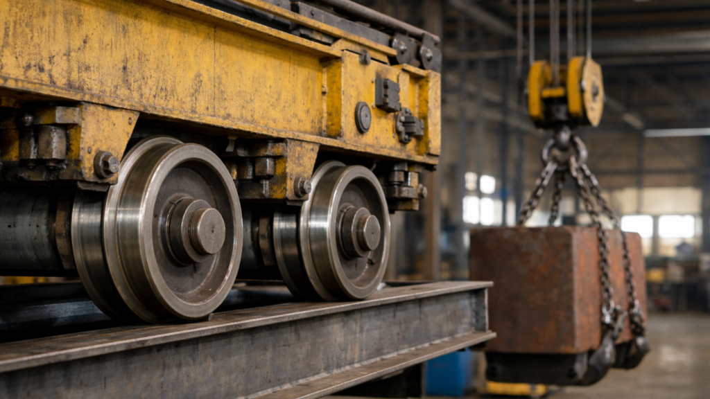
Static Vertical Wheel Loads
The starting point is determination of static vertical wheel loads.
For overhead travelling cranes, wheel reactions depend on:
- Crane bridge self-weight
- Trolley weight
- Hoisted load
- Position of the trolley
- Span length
When the trolley is positioned close to one end of the bridge, one wheel line carries maximum reaction, while the opposite side carries reduced load.
This produces:
- Maximum static wheel load
- Maximum accompanying wheel load
- Minimum static wheel load
- Minimum accompanying wheel load
Each must be calculated separately.
Why Accompanying Wheel Load Matters
When one wheel reaches maximum reaction, the opposite wheel does not drop to zero. Instead, it carries a reduced but non-negligible accompanying load.
This accompanying load influences:
- Support reactions
- Bending moment distribution
- Rail beam torsion
- Uplift checks
In certain configurations, minimum accompanying loads may approach uplift conditions, especially when horizontal forces are combined.
Inclusion of Dynamic Factors
Static wheel loads are then amplified using relevant dynamic factors 𝜑.
For example:
- φ1 applied to self-weight
- φ2 applied to hoisted load
This produces dynamic maximum wheel loads that are used for ultimate limit state checks.
Dynamic amplification often governs final design forces.
Load Groups in EN 1991-3
EN 1991-3 defines several load groups that combine vertical loads with dynamic effects.
Typical groups include:
- Lifting condition
- Self-weight condition
- Rapid load release
- Test load condition
Each group leads to different maximum and minimum wheel reactions. Structural design must verify all relevant groups.
Engineering Consequences
Failure to check minimum wheel loads may result in:
- Underestimated uplift at supports
- Incorrect anchor design
- Unverified stability under combined horizontal forces
At the same time, maximum wheel loads govern:
- Bending resistance of runway beams
- Bearing capacity of supports
- Local rail stresses
Both extremes are structurally significant.
Conclusion
Crane wheel loads are inherently non-uniform and vary with trolley position and operating condition. EN 1991-3 therefore requires calculation of both maximum and minimum accompanying wheel loads, ensuring that the full range of structural effects is captured.
Maximum reactions govern strength and bending checks, while minimum reactions are essential for stability and uplift verification. A complete crane load assessment must therefore consider both extremes to achieve a safe and consistent structural design.